Contact Person: kevin
Tel:86-0755-8605 7437
Fax:86-0755-8605 7437-801
Tel:86-180 9892 8927
E-mail: kevin_wang@bestpowersz.com
QQ:1594542830
抖音号:1951627563
wwd20201002
网址:http://www.bestpowersz.com
Add:Changfeng Industrial Park, Fenghuang Street, Guangming District, Shenzhen, Guangdong Province, Changfeng Industrial Zone, 6 Changfeng Industrial Zone
Explanation of current sharing circuit
Firstly, let me understand why there is a current sharing circuit. When designing a power supply, there are requirements for the output current range and output voltage. The power is generally given, but the requirements for power vary depending on the application. For example, a large communication system power supply may require several hundred kilowatts. If I design a power supply, the stress of the applied devices is very high. In order to reduce the stress of the devices, One way to sample and distribute is to connect multiple power sources in parallel, for example, 10 10KW power sources can achieve 100KW. It is much easier to make a 10KW power supply than a 100KW one. So it needs to be applied to parallel connection, and voltage source parallel connection requires current sharing technology. Why do we need current sharing? For example, if we all use 5V output power supplies and connect them directly, it's okay in theory. However, in practice, switch power supplies always have an error range, such as 5V power supplies may be 5.01V or 4.99V, which is within our allowable range. If a 5. V power supply is connected in parallel with a 5.01V power supply, it may cause the output of the 5.01V power supply to be overloaded, while the output of the 5V power supply is under light load. This is what we do not want to see. We hope that the two power supplies are loaded the same, which is the best. Why is there an overload and a light load? This is because our switching power supply has a feedback system. When two power supplies are connected in parallel, the 5V and 5.01V are directly connected in parallel, Let's take a look at the picture below,
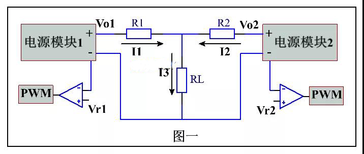
When the output of power module 1 and power module 2 is the same and connected in parallel to the load RL, the output current will also be different due to the wire resistance R1 and R2. If the resistance of R1 and R2 is the same, and Vo1 is smaller than Vo2, it may cause Vo1 to remain empty. The reason for the voltage difference between the two power modules may be due to the error between the reference voltages of Vr1 and Vr2. If the output voltage is different due to these two reference voltages, when connected in parallel, the output voltage of the module with a small output voltage is forcibly clamped to the voltage above the load. Only when the voltage of Vo2-I2 * R2 on the load is less than Vo1 can module 1 have current flowing to the load.
What kind of sampling method can we use to equalize the current of the power module? If we find a way to lower the output voltage of Module 2 or increase the voltage of Module 1, can we achieve less load on Module 2 and more load on Module 1.
So there are four averaging methods.
01. Output impedance method
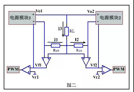
As shown in Figure 2, when the current of a module is relatively large, after being amplified by the Current loop, it is superimposed with the Vf pin of the voltage loop. The output voltage of the module with high output voltage becomes larger due to the load and large output current. The output voltage of the Current loop becomes higher. Because our power source is negative feedback, the output voltage becomes lower after the adjustment of the whole system. This is the output impedance amplifier. The circuit is simple, But as the output current increases, the voltage decreases, resulting in a decrease in the accuracy of the output voltage.
02. Master slave setting method
The master-slave setting method is to manually set a master module, and all modules use this module as a reference to output current. The working diagram of a master-slave setting current sharing method is shown in Figure 3
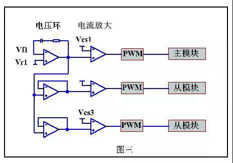
From the above figure, it can be seen that in this working mode, multiple power module units are connected in parallel. One power module operates in voltage source mode, while the other power module operates in current source mode. In fact, the voltage loop (outer loop) and the Current loop (inner loop) form a current controlled double loop control, or a voltage controlled current source. This current sharing method specifies the main module during our design process. If there is a problem with the main module during operation, the entire system will be paralyzed.
03. Average current method
The average current method first needs to obtain an average current value, which is the current value obtained by dividing the total load current by the total number of modules. The currents of each module are compared with this average current. If the module current is greater than the average current, the output voltage of the module is lowered. Conversely, the output voltage of the module is raised to achieve consistent output current for each module. In the average current method, by connecting the output currents of all modules together through a resistor, the average value of the output currents of all modules can be obtained. This point is called the current sharing bus. If the module power supply is less than the voltage of the current sharing bus at the output time, it is amplified by an error arrester and superimposed with the reference voltage to increase the output voltage and increase the output current.
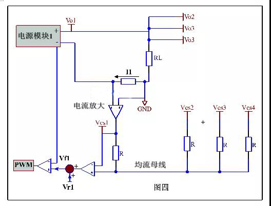
04. Peak current method
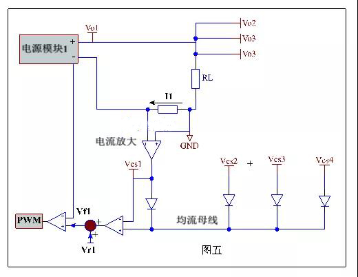
This is a method of automatically setting the main module and slave module, that is, when n modules are connected in parallel, the module that outputs the maximum current will automatically become the main module, while the other modules are slave modules. Therefore, the current of the voltage modules will be adjusted in order to correct the uneven load current,
This method, also known as the automatic master-slave method, is achieved by converting the current sharing busbar resistor into a diode, so that the module with the highest output current becomes the main module, and all other modules move closer to the main module.